What problem did I see?
Most demonstrations of autonomous vehicles I could find online were either extremely high-budget (self-driving cars with LiDAR systems costing tens of thousands of dollars) or extremely simple (line-following robots that had no real understanding of their environment). I wanted to explore the middle ground: what can a small, low-cost system actually perceive and decide on its own?
The core question wasn't "can I build a robot that moves" — that's straightforward. The real question was: can a machine develop a usable model of its immediate physical environment using only inexpensive sensors?
Why did I care?
Autonomous systems feel like one of the most consequential areas of engineering in the next decade — not just for self-driving cars, but for delivery, accessibility, agriculture, and industrial automation. I wanted to understand how these systems actually work at a low level, not just use an existing API.
I was also frustrated by tutorials that showed the end result without explaining why certain design decisions were made. I wanted to make mistakes myself, trace them to their root cause, and develop a better intuition for how computer vision and embedded control interact.
What did I build?
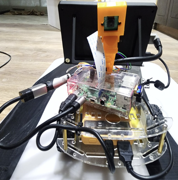
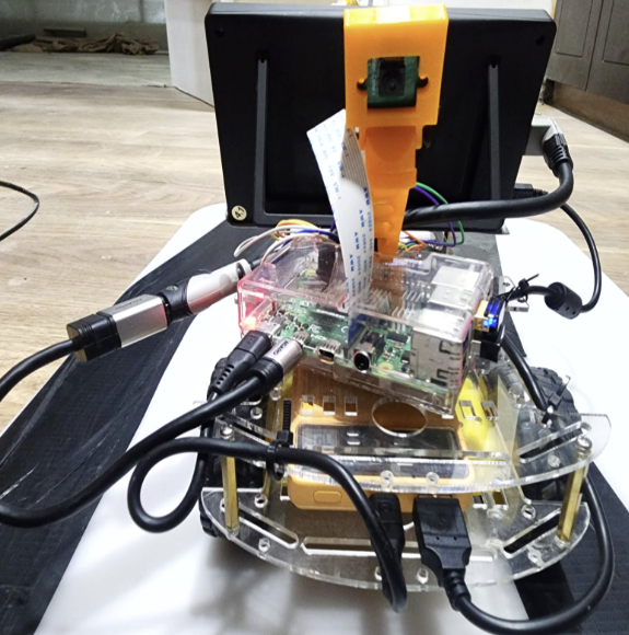
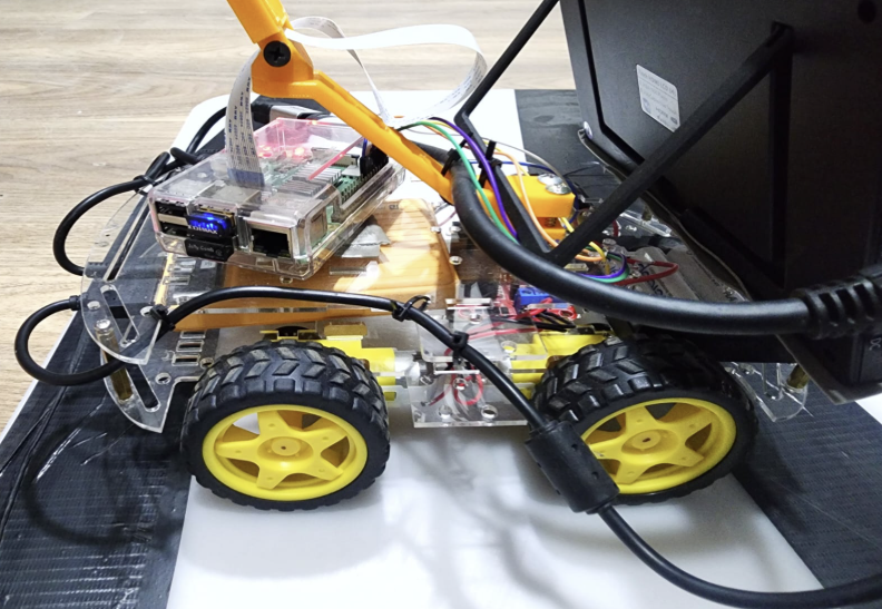
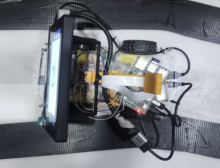
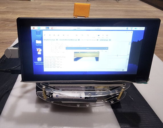
I built a small wheeled vehicle with the following system architecture:
- A camera module for real-time image capture
- Used Raspberry Pi for sensor reading and motor control
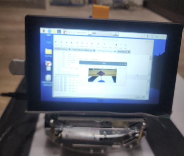
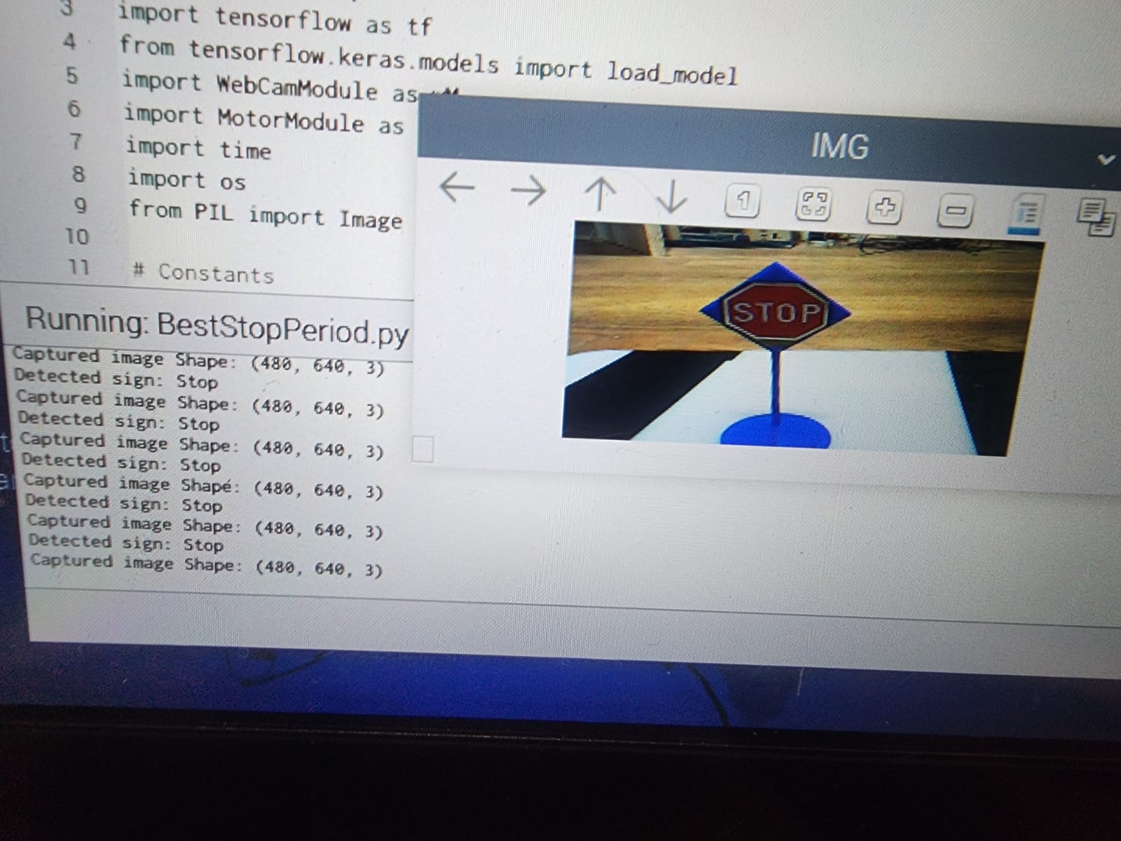
- A computer vision pipeline (using OpenCV) for lane or path detection
- A basic decision loop: perceive → classify → act
The vehicle was designed to navigate a controlled indoor environment — detecting obstacles, making rudimentary turning decisions, and attempting to follow a path.
Bill of Materials
What went wrong?
Almost everything, in the right order.
The first version used sensor readings that I assumed would be stable — they weren't. Ultrasonic sensors at certain angles produce spurious reflections. My distance estimates were inconsistent, which caused the vehicle to make incorrect turning decisions.
The computer vision pipeline performed well in consistent lighting but broke down completely when I moved the vehicle near a window. I had trained my intuition on controlled conditions and the real environment immediately revealed this gap.
Processing latency was another issue. The gap between sensor reading and motor response was large enough at certain speeds that the vehicle was already past an obstacle by the time it received the signal to turn. I had underestimated how much timing matters in embedded systems.
What did I learn?
The most important lesson was that sensor data is not truth. It is a noisy, context-dependent signal that has to be interpreted, filtered, and validated before it can support reliable decisions. This sounds obvious in retrospect; it wasn't obvious before I built something that broke because of it.
I also learned that the interface between software and hardware is the hardest part of embedded engineering. Writing the vision pipeline was relatively straightforward. Making it run fast enough, on real hardware, in a real environment — that required a different kind of thinking.
If I rebuilt this today, I would add a Kalman filter for sensor fusion, test in multiple lighting conditions from day one, and instrument the timing of every processing step before tuning anything else.